| Example Sequence 1
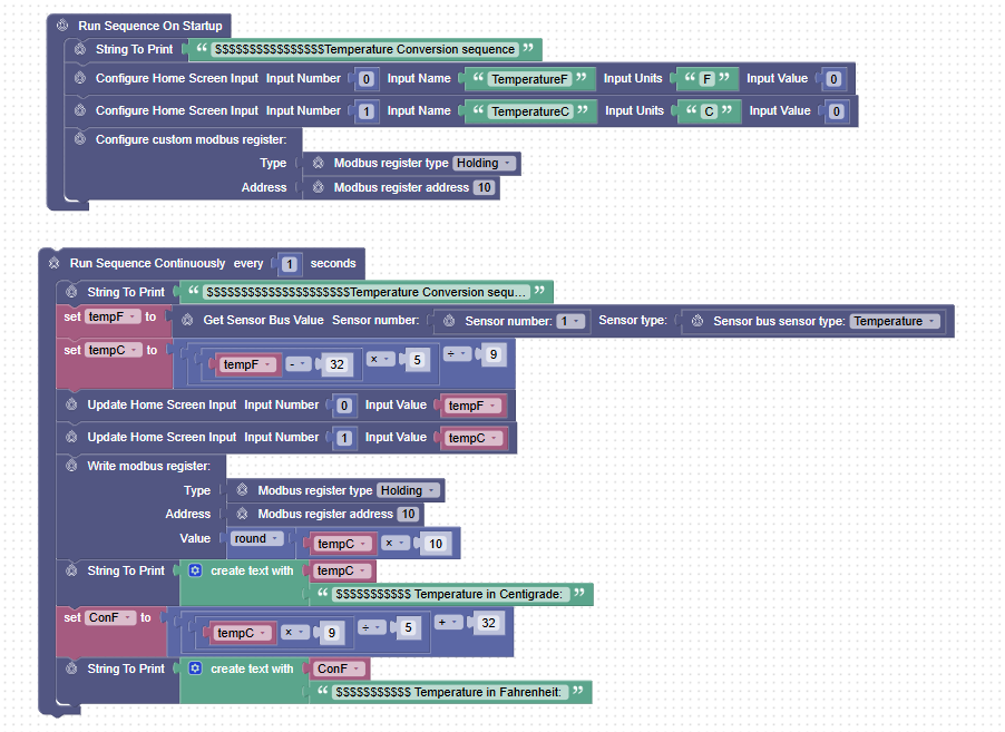
The sequence is created to read the measured temperature from an RTH in Fahrenheit, convert it to a Temperature in Celsius, and display it as inputs on the home screen.
First Part of the Sequence:
| Step |
Block |
Actions |
| Step 1 |
Sequence Block (Mandatory) |
- To apply running the sequence on start up.
|
| Step 2 |
String to Print
|
-
- To define a name for the sequence
|
| Step 3 |
Configure Home Screen Input 0 |
To Configure a parameter on the home page:
-
- With a field name TemperatureF
- Input Unit F
- Input Value 0
|
| Step 4 |
Configure Home Screen Input 1 |
To Configure a parameter on the home page:
-
- With a field name TemperatureC
- Input Unit C
- Input Value 0
|
| Step 5 |
Configure Custom Modbus Register |
To configure a custom modbus register with
- Register Type Holding
- Register Address 0
|
Second Part of the Sequence:
The Table below talks about the steps and the blocks used in the sequence to achieve the use case.
| Step |
Block |
Actions |
| Step 1 |
Sequence Block (Mandatory) |
- To apply running the sequence every second continuously.
|
| Step 2 |
String to Print
|
- To define a name for the sequence
|
| Step 3 |
Set Temp F function
|
-
- Create a variable Temp F
- Get the Sensor Bus value from sensor bus 1, and type Temperature sensor.
- Assing the value to the Variable Temp F
|
| Step 4 |
Set Temp C function |
-
- Create a variable Temp C
- Convert the Temp F value measured to Celsius using the formula.
- Assing the converted value back to Variable Temp C
|
| Step 5 |
Update Home screen predefined block 0 |
- Update the home screen Input that was configured in the previous table,
- For the input number 0, set the input value field to variable Temp F
|
| Step 6 |
Update Home screen predefined block 1 |
- Update the home screen Input that was configured in the previous table,
- For the input number 1, set the input value field to variable Temp C
|
| Step 7 |
Write Modbus Register predefined block |
- Write to the Modbus register configured in the previous table, for the register type Holding, and the registered address 10
- With a value rounding of the TempC value from float to integer.
|
| Step 8 |
String to Print |
- Define a name for the step
|
| Step 9 |
Set ConF |
-
- Create a variable ConF
- Convert the TempC value in Celsius back to Fahrenheit using the formula.
- Assing the converted Fahrenheit value to the Variable ConF.
|
| Step 10 |
String to Print |
- Display the converted Fahrenheit value with a name Temperature in Fahrenheit.
|
| Capability to Write to a Modbus Register
Step 5 in the first part of the sequence table, and steps 7 to 10 in the second, is a clearly illustrated capability of the device in the mode, to configure Modbus register, and write a value to it.
The same can be visualized as shown in a Modbus master, as below.
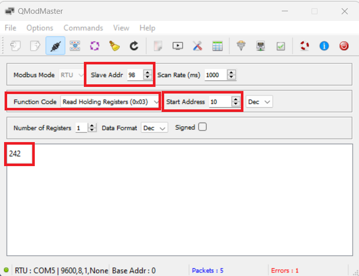
When tried to read the holding register value for the address 10 the value populated as per the sequence step.
| Example Sequence 2
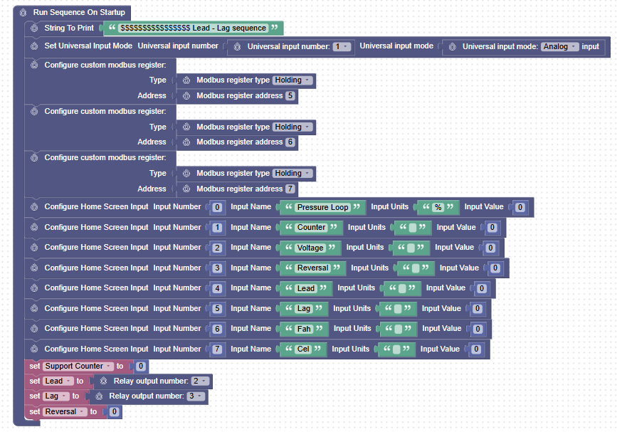
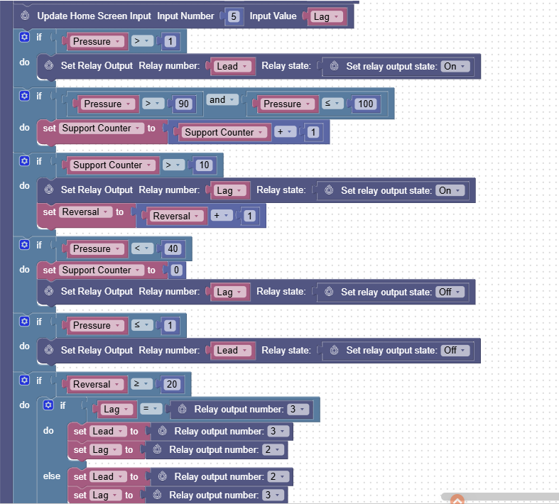
The sequence is created for one of the most frequently used chiller sequences for lead, lag pumps in a unit. According to this sequence, the lead and lag pumps switchover (Lead becomes Lag, Lag becomes Lead) from time to time based on certain conditions.
The Table below talks about the steps and the blocks used in the sequence to achieve the use case.
First Part of the Sequence:
| Step |
Block |
Actions |
| Step 1 |
Sequence Block (Mandatory) |
- To apply running the sequence on startup.
|
| Step 2 |
String to Print
|
-
- To define a name for the sequence
|
| Step 3 |
Configure Custom Modbus Register |
To configure a custom Modbus register with
- Register Type Holding
- Register Address 5
|
| Step 4 |
Configure Custom Modbus Register |
To configure a custom Modbus register with
- Register Type Holding
- Register Address 6
|
| Step 5 |
Configure Custom Modbus Register |
To configure a custom Modbus register with
- Register Type Holding
- Register Address 7
|
| Step 6 |
Configure Home Screen Input 0 |
To Configure a parameter on the home page:
-
- With a field named Pressure Loop
- Input Unit %
- Input Value 0
|
| Step 7 |
Configure Home Screen Input 1 |
To Configure a parameter on the home page:
-
- With a field named Counter
- Input Unit NA
- Input Value 0
|
| Step 8 |
Configure Home Screen Input 2 |
To Configure a parameter on the home page:
-
- With a field named Voltage
- Input Unit NA
- Input Value 0
|
| Step 9 |
Configure Home Screen Input 3 |
To Configure a parameter on the home page:
-
- With a field named Reversal
- Input Unit NA
- Input Value 0
|
| Step 10 |
Configure Home Screen Input 4 |
To Configure a parameter on the home page:
-
- With a field named Lead
- Input Unit NA
- Input Value 0
|
| Step 11 |
Configure Home Screen Input 5 |
To Configure a parameter on the home page:
-
- With a field named Lag
- Input Unit NA
- Input Value 0
|
| Step 12 |
Configure Home Screen Input 6 |
To Configure a parameter on the home page:
-
- With a field named Fah
- Input Unit NA
- Input Value 0
|
| Step 13 |
Configure Home Screen Input 7 |
To Configure a parameter on the home page:
-
- With a field named Cel
- Input Unit NA
- Input Value 0
|
| Step 14 |
Set Support Counter function |
-
- Create a variable Support Counter
- Assing a value "0" to the Variable Support Counter
|
| Step 15 |
Set Lead function |
-
- Create a variable Lead
- Use a Relay Output Number predefined block
- Set the Relay Output Number to 2
- Assing the Value from the Realy Output 2 to variable Lead.
|
| Step 16 |
Set Lag function |
-
- Create a variable Lag
- Use a Relay Output Number predefined block
- Set the Relay Output Number to 3
- Assing the Value from the Relay Output 3 to variable Lag.
|
| Step 17 |
Set Reversal function |
-
- Create a variable Reversal
- Assing a value "0" to the Variable Reversal.
|
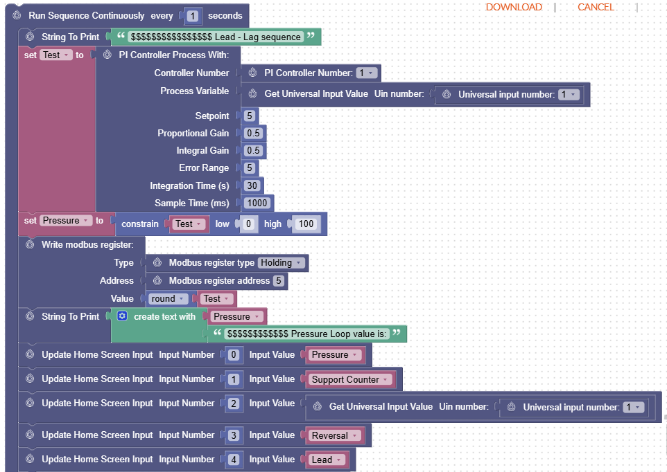

The Table below talks about the steps and the blocks used in the sequence to achieve the use case.
Second Part of the Sequence:
| Step |
Block |
Actions |
| Step 1 |
Sequence Block (Mandatory) |
- To apply running the sequence every second continuously.
|
| Step 2 |
String to Print
|
- To define a name for the sequence
|
| Step 3 |
Set Test function
|
-
- Create a variable Test
- Use a PI controller process predefined block.
- Set the PI controller number.
- Set the Process Variable to the measured value from the Universal Input 1.
- Set the following PI loop calculation requirements as tuner parameters and other values.
- SetPoint
- Proportional Gain
- Integral Gain
- Error Range
- Integration Time (s)
- Sample Time (ms)
-
- Assing the PI Loop Value to variable Test
|
| Step 4 |
Set Pressure function |
-
- Create a variable Pressure
- Use a Constrain Block to set the minimum and maximum for the variable Test
- Convert the Temp F value measured to Celsius using the formula.
- Assing the converted value back to Variable Temp C
|
| Step 5 |
Write Modbus Register predefined block |
- Write to the Modbus register configured in the previous table, for the register type Holding, and the registered address 5
- With a value rounding of the Test value
|
| Step 6 |
String to Print |
- To display the pressure loop value with the pressure value calculated.
|
| Step 7 |
Update Home screen predefined block 0 |
- Update the home screen Input that was configured in the previous table,
- For input number 0, set the input value field to variable Pressure.
|
| Step 8 |
Update Home screen predefined block 1 |
- Update the home screen Input that was configured in the previous table,
- For input number 1, set the input value field to the variable Support Counter.
|
| Step 9 |
Update Home screen predefined block 2 |
- Update the home screen Input that was configured in the previous table.
- Use Get Universal Input Value Uin number, to get the measured value from Univeral Input 1.
- For input number 2, set the input value field to the value measured using the previous step.
|
| Step 10 |
Update Home screen predefined block 3 |
- Update the home screen Input that was configured in the previous table,
- For input number 3, set the input value field to variable Reversal.
|
| Step 11 |
Update Home screen predefined block 4 |
- Update the home screen Input that was configured in the previous table,
- For input number 4, set the input value field to variable Lead.
|
| Step 12 |
Update Home screen predefined block 5 |
- Update the home screen Input that was configured in the previous table,
- For the input number 5, set the input value field to variable Lag.
|
| Step 13 |
If Logic Block |
- If the variable Pressure value is > 1
- Use the Set Relay Output Relay Number & Set Relay Output State predefined blocks, to set the relay output assigned to variable Lead to ON.
|
| Step 14 |
If Logic Block |
- If the variable Pressure value is > 1 & less than or equal to 100.
- Use the Set Support Counter function, and increment the Support Counter by 1.
|
| Step 15 |
If Logic Block |
- If the variable Support Counter is > 10.
- Use the Set Relay Output Relay Number & Set Relay Output State predefined blocks, to set the relay output assigned to variable Lag to ON.
- Use the Set Reversal function, and increment the Reversal by 1.
|
| Step 16 |
If Logic Block |
- If the variable Pressure value is < 40.
- Use the Set Support Counter function, and set the Support Counter to 0.
- Use the Set Relay Output Relay Number & Set Relay Output State predefined blocks, to set the relay output assigned to variable Lag to Off.
|
| Step 16 |
If Logic Block |
- If the variable Reversal is greater than or equal to 20.
- Use the Relay Output Number predefined block to check if the Relay Output number 3 is assigned to the variable Lag,
| If variable Lag is = Relay Output number 3 |
- Use the Set Lead & Relay Output Number predefined block to Assing the Realy Output Number 3 to Variable Lead
- Use the Set Lead & Relay Output Number predefined block to Assing the Realy Output Number 2 to Variable Lag
|
|
If variable Lag is not equal to Relay Output number 3
|
- Use the Set Lead & Relay Output Number predefined block to Assing the Realy Output Number 2 to Variable Lead
- Use the Set Lead & Relay Output Number predefined block to Assing the Realy Output Number 3 to Variable Lag
|
|
| Step 17 |
Set Reversal function |
- Use the Set Reversal function, and set Reversal to 0.
|
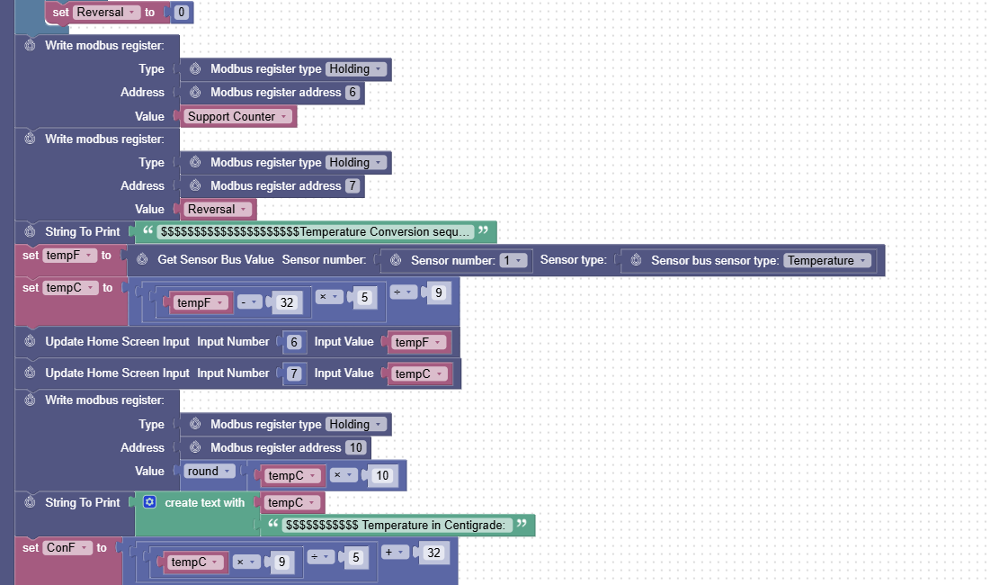
| Step 18 |
Write Modbus Register predefined block |
- Write to the Modbus register configured in the previous table, for the register type Holding, and register address 6.
- With a value of the variable Support Counter value.
|
| Step 19 |
Write Modbus Register predefined block |
- Write to the Modbus register configured in the previous table, for the register type Holding, and register address 7.
- With a value of the variable Reversal value.
|
| Step 18 |
If Logic Block |
- If the variable Pressure value is less than or equal to 1.
- Use the Set Relay Output Relay Number & Set Relay Output State predefined blocks, to set the relay output assigned to the variable Lead to Off.
|
| Step 19 |
String to Print |
- Define a name for the step
|
| Step 20 |
Set TempF function |
- Create a Variable TempF
- Use the set TempF function, Get the Sensor Value, Sensor number with Sensor Type, and Sensor Bus Sensor Type, and Set variable TempF to value from Temperature sensor at sensor address 1.
|
| Step 21 |
Set TempC function |
-
- Create a variable TempC
- Convert the TempF value in Fahrenheit to Celsius using the formula.
- Assing the converted Celsius value to the Variable TempC.
|
| Step 22 |
Update Home screen predefined block |
- Update the home screen Input that was configured in the previous table,
- For the input number 6, set the input value field to variable Temp F
|
| Step 23 |
Update Home screen predefined block |
- Update the home screen Input that was configured in the previous table,
- For the input number 7, set the input value field to variable Temp C
|
| Step 24 |
Write Modbus Register predefined block |
- Write to the Modbus register configured in the previous table, for the register type Holding, and the registered address 10
- With a value rounding of the TempC value from float to integer.
|
| Step 8 |
String to Print |
- Define a name for the step
|
| Step 9 |
Set ConF |
-
- Create a variable ConF
- Convert the TempC value in Celsius back to Fahrenheit using the formula.
- Assing the converted Fahrenheit value to the Variable ConF.
|
| Step 10 |
String to Print |
- Display the converted Fahrenheit value with a name Temperature in Fahrenheit.
|
| Real Time Clock (RTC) Support for Time bound Sequences
The sequencer for the edge devices, now supports blocks to include real time clock to favor time bound sequence steps.
The below table talks about the blocks introduced:
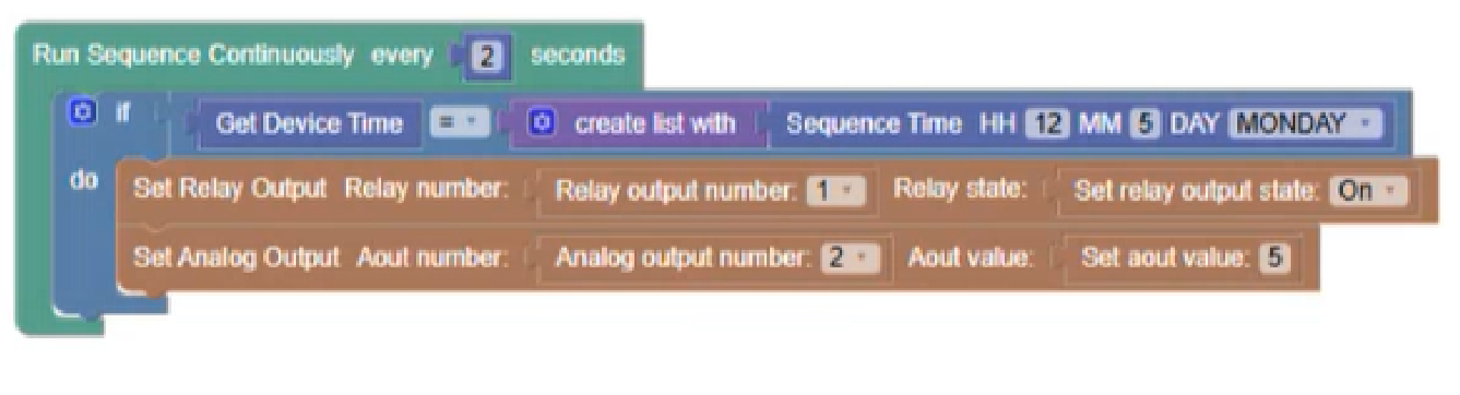
Example:
Below is an example where a sequence id defined to set the Analog out value to a particular volt at a particular time of the day.
Setting Device Time:

| Step |
Block |
Actions |
| Step 1 |
Sequence Block (Mandatory) |
- To apply running the sequence on start up
|
| Step 2 |
Enable Fail Safe
|
- Set Enable fail safe to false
|
| Step 3 |
Set Device time
|
- Set device time in Hours, Minutes along with the day of the week.
|
Time bound sequence creation:
| Step |
Block |
Actions |
| Step 1 |
Sequence Block (Mandatory) |
- To apply running the sequence every 2-minute start up.
|
| Step 2 |
If block
|
- Set the sequence time is required hour & minutes along with the day of the week.
- Create a list with the set sequence time.
- Get the device time
If the device time is equal to the set sequence time.
- Set the Relay output, for Relay output number 1, to stateOn
- Set the Analog output, for Analog output number 2, to value 5V
|

Comments
0 comments
Please sign in to leave a comment.